well i got a few:
10x of those motion sensors:

1x light sensor that measures the light level:

2x wall remotes to use “old” wall switches.

2x LED strip dimmer

1x kWh pulse meter

And the gateway

Share your MySensors project
well i got a few:
10x of those motion sensors:
1x light sensor that measures the light level:
2x wall remotes to use “old” wall switches.
2x LED strip dimmer
1x kWh pulse meter
And the gateway
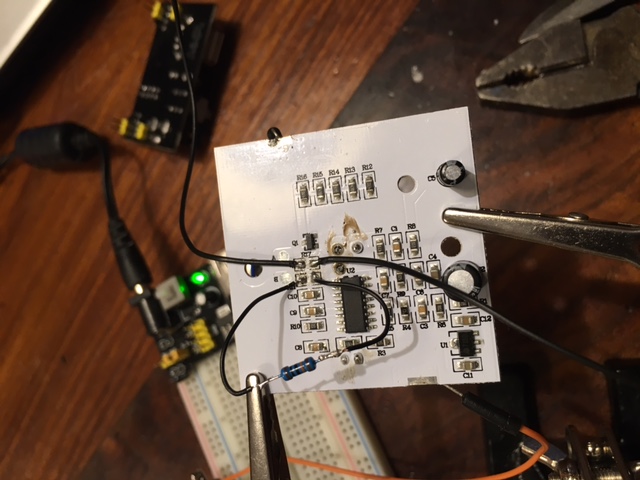
I had a problem where one one my fountains could not receive the 433Mhz messages from homeduino. So I created a MySensors KaKu (Klik aan Klik uit) transmitter.
It has a default address and you can use different dimmers/switches by using a different sensor id. In this case the sensor id == kaku unit.
This sketch works for KaKu, CoCo, Elro …
// ********** CONFIG **********************************

    #define MY_NODE_ID 16       // ID of node
    #define TX_PIN 8              // Pin connected to the 433MHz transmitter
    #define ADDRESS 38484         // KaKu ID

    #define MY_DEBUG              // Debug
    #define MY_REPEATER_FEATURE   // Repeater

// ****************************************************

#define MY_RADIO_NRF24
#include <NewRemoteTransmitter.h>
#include <SPI.h>
#include <MySensor.h>

NewRemoteTransmitter transmitter(ADDRESS, TX_PIN, 260, 3);

void setup() {
  sendSketchInfo("KaKu transmitter", "1.0");
}

void loop() {
}

void receive(const MyMessage &message) {
  // If switch
  if (message.type==V_STATUS) {
    Serial.print("Switching to ");
    Serial.println(message.getBool());
    transmitter.sendUnit(message.sensor, message.getBool());
  }
  // If dimmer
  if (message.type==V_PERCENTAGE) {
    int dimlevel = round(0.15 * atoi(message.data));
    Serial.print("Dimming to ");
    Serial.println(dimlevel);
    transmitter.sendDim(message.sensor, dimlevel);
  }
}
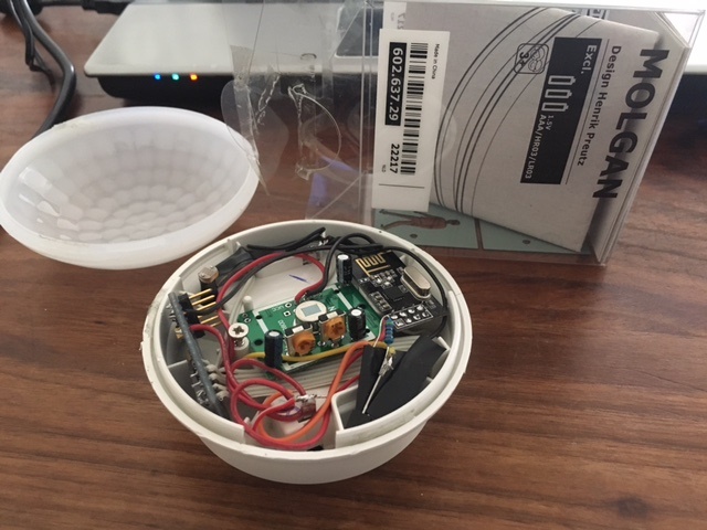
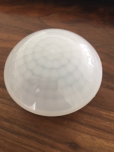
Hi, just wanted to show you a Multi sensor PIR based on the IKEA Molgan. I have used the mysensors procol for it. During my “investigation” I destroyed the original IKEA pir, but next one I am going to use the original Ikea PIR. The sensor runs on two AAA and has a PIR, LDR Light sensor and a dallas temp sensor. I want to add some pictures, how do I add them without uploading them to a seperate server?
I have uploaded them to the mysensors page: [http://forum.mysensors.org/topic/3756/multisensor-pir-based-on-ikea-molgan]
Love this one! Need to buy some of those molgans ")
very nice project!! and those molgan’s are relatively cheap with 5 Euro/piece.
gonna get my hands on them when i am at ikea next time.
pimatic v0.9 has been released!
Support Pimatic and get some free stickers
Like us on Facebook
make it so !
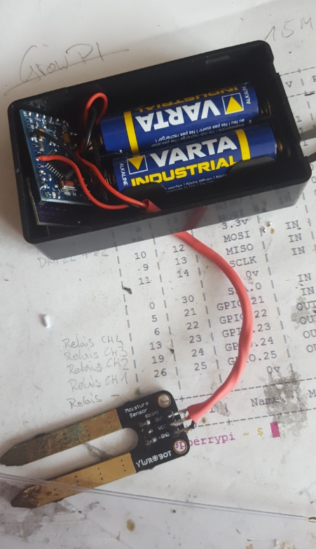
Yesterday i build some more sensors
based on
3,3V Arduino Pro mini (@sweebee 's Pro-Mini-Mod’s), 1,20€/p
Mini NRF24L01+ SMD 1.27MM, 1,50€/p
4,85€ for Baseparts, i think thats okay
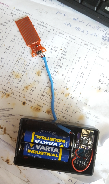
My Soil Moisture Sensors:
Sketch:
#include <MySensor.h>
#include <SPI.h>
#include <readVcc.h>

// ********** CONFIG **********************************

    #define MY_RADIO_NRF24
    #define NODE_ID 3         // ID of node
    #define CHILD_ID 3            // ID of sensor
    #define INPUT_PIN 3             // OUT-Pin of Moisture Sensor
    #define VCC_PIN 4              // VCC-Pin of Moisture Sensor

    #define MIN_V 2000            // empty voltage (0%)
    #define MAX_V 3200            // full voltage (100%)

// ****************************************************

MyMessage msg(CHILD_ID, V_LEVEL);
MySensor node;

int oldBatteryPcnt;
int sentValue;
int forceSend = 0;

void setup()
{
  node.begin(NULL, NODE_ID, false);
  node.sendSketchInfo("Moisture Sensor", "1.0");
  node.present(CHILD_ID, S_MOISTURE);
  pinMode(INPUT_PIN, INPUT);
  pinMode(VCC_PIN, OUTPUT);
}

void loop()
{
  digitalWrite(VCC_PIN, HIGH); // Turn on Moisture sensor
  // Get Percent
  int value = analogRead(INPUT_PIN);  // Get Moisture
  int percent = map(value, 0, 700, 0, 100);
    resend(msg.set(percent), 2); // Send PIR status to gateway
    sentValue = percent;


  // Send batterylevel
  sendBattery();

  digitalWrite(VCC_PIN, LOW); // Turn off Moisture sensor

  // Sleep 1 hour
  node.sleep(3600000);      // Sending every hour to Gateway
}

// FUNCTIONS

void sendBattery() // Send battery percentage to GW
{
  forceSend++;
  int batteryPcnt = min(map(readVcc(), MIN_V, MAX_V, 0, 100), 100); // Get VCC and convert to percentage
  if (batteryPcnt != oldBatteryPcnt || forceSend >= 20) { // If battery percentage has changed
    node.sendBatteryLevel(batteryPcnt); // Send battery percentage to gateway
    oldBatteryPcnt = batteryPcnt;
    forceSend = 0;
  }
}

void resend(MyMessage &msg, int repeats) // Resend messages if not received by GW
{
  int repeat = 0;
  int repeatDelay = 0;
  boolean ack = false;

  while ((ack == false) and (repeat < repeats)) {
    if (node.send(msg)) {
      ack = true;
    } else {
      ack = false;
      repeatDelay += 100;
    }
    repeat++;
    delay(repeatDelay);
  }
}
Pimatic-device-config
    {
      "class": "MySensorsMulti",
      "id": "Soil_Gummibaum",
      "name": "Erdfeuchte Gummibaum",
      "attributes": [
        {
          "name": "Erdfeuchte Gummibaum",
          "nodeid": 3,
          "sensorid": 3,
          "type": "integer",
          "unit": "%",
          "sensortype": 37
        },
        {
          "name": "Battery",
          "nodeid": 3,
          "type": "battery",
          "unit": "%"
        }
      ]
    }
and how it looks like

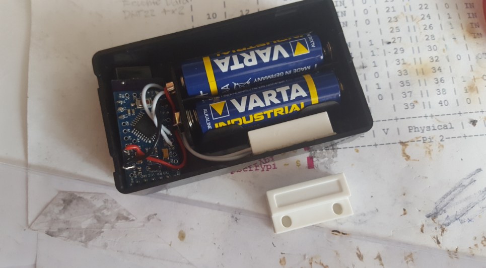
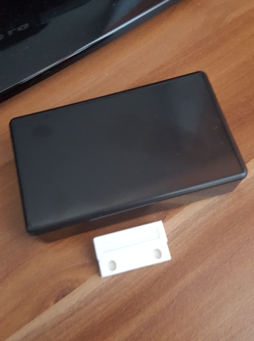
My Door/Windos Contact Sensors
Sketch:
#include <MySensor.h>
#include <SPI.h>
#include <readVcc.h>

// ********** CONFIG **********************************

    #define MY_RADIO_NRF24
    #define NODE_ID 8          // ID of node
    #define CHILD_ID 8            // ID of sensor
    #define REED_PIN 3             // Pin connected to the Reed-contact, other to GND

    #define MIN_V 2000            // empty voltage (0%)
    #define MAX_V 3200            // full voltage (100%)

// ****************************************************

MyMessage msg(CHILD_ID, V_TRIPPED);
MySensor node;

int oldBatteryPcnt;
int sentValue;
int forceSend = 0;

void setup()
{
  node.begin(NULL, NODE_ID, false);
  node.sendSketchInfo("Contact Sensor", "1.2");
  node.present(CHILD_ID, S_MOTION);
  pinMode(REED_PIN, INPUT);
  digitalWrite(REED_PIN, HIGH);
}

void loop()
{

  // Get REED
  int value = digitalRead(REED_PIN); // Get value of State
  if (value != sentValue) { // If status of reedcontact has changed
    resend(msg.set(value), 5); // Send reedcontact status to gateway
    sentValue = value;
  }

  // Send batterylevel
  sendBattery();

  // Sleep until something happens with the sensor
  node.sleep(REED_PIN-2, CHANGE);
}

// FUNCTIONS

void sendBattery() // Send battery percentage to GW
{
  forceSend++;
  int batteryPcnt = min(map(readVcc(), MIN_V, MAX_V, 0, 100), 100); // Get VCC and convert to percentage
  if (batteryPcnt != oldBatteryPcnt || forceSend >= 20) { // If battery percentage has changed
    node.sendBatteryLevel(batteryPcnt); // Send battery percentage to gateway
    oldBatteryPcnt = batteryPcnt;
    forceSend = 0;
  }
}

void resend(MyMessage &msg, int repeats) // Resend messages if not received by GW
{
  int repeat = 0;
  int repeatDelay = 0;
  boolean ack = false;

  while ((ack == false) and (repeat < repeats)) {
    if (node.send(msg)) {
      ack = true;
    } else {
      ack = false;
      repeatDelay += 100;
    }
    repeat++;
    delay(repeatDelay);
  }
}
Pimatic-device-config
    {
      "id": "MySensors_Contact_Sleeproom",
      "name": "Fenster Kinderzimmer",
      "class": "MySensorsButton",
      "nodeid": 8,
      "sensorid": 8,
      "batterySensor": true
    }
and how it looks like

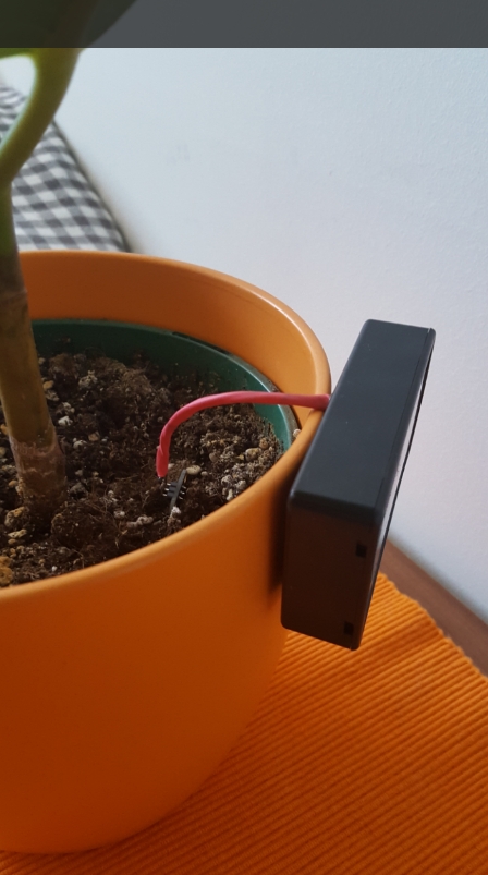
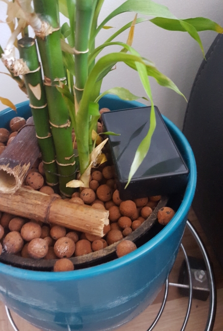
My Water-gauge Sensor
Sketch
#include <MySensor.h>
#include <SPI.h>
#include <readVcc.h>

// ********** CONFIG **********************************

    #define MY_RADIO_NRF24
    #define NODE_ID 6         // ID of node
    #define CHILD_ID 6            // ID of sensor
    #define INPUT_PIN 1             // OUT-Pin of Sensor
    #define VCC_PIN 4              // VCC-Pin of Sensor

    #define MIN_V 2000            // empty voltage (0%)
    #define MAX_V 3200            // full voltage (100%)

// ****************************************************

MyMessage msg(CHILD_ID, V_LEVEL);
MySensor node;

int oldBatteryPcnt;
int sentValue;
int forceSend = 0;

void setup()
{
  node.begin(NULL, NODE_ID, false);
  node.sendSketchInfo("Water Sensor", "1.0");
  node.present(CHILD_ID, S_MOISTURE);
  pinMode(INPUT_PIN, INPUT);
  pinMode(VCC_PIN, OUTPUT);
}

void loop()
{
  digitalWrite(VCC_PIN, HIGH); // Turn on Moisture sensor
  // Get Percent
  int value = analogRead(INPUT_PIN);  // Get Moisture
  int percent = map(value, 0, 1023, 0, 100);
    resend(msg.set(percent), 2); // Send PIR status to gateway
    sentValue = percent;


  // Send batterylevel
  sendBattery();

  digitalWrite(VCC_PIN, LOW); // Turn on Moisture sensor

  // Sleep 4 hours
  node.sleep(14400000);
}

// FUNCTIONS

void sendBattery() // Send battery percentage to GW
{
  forceSend++;
  int batteryPcnt = min(map(readVcc(), MIN_V, MAX_V, 0, 100), 100); // Get VCC and convert to percentage
  if (batteryPcnt != oldBatteryPcnt || forceSend >= 20) { // If battery percentage has changed
    node.sendBatteryLevel(batteryPcnt); // Send battery percentage to gateway
    oldBatteryPcnt = batteryPcnt;
    forceSend = 0;
  }
}

void resend(MyMessage &msg, int repeats) // Resend messages if not received by GW
{
  int repeat = 0;
  int repeatDelay = 0;
  boolean ack = false;

  while ((ack == false) and (repeat < repeats)) {
    if (node.send(msg)) {
      ack = true;
    } else {
      ack = false;
      repeatDelay += 100;
    }
    repeat++;
    delay(repeatDelay);
  }
}
Pimatic device config
    {
      "class": "MySensorsMulti",
      "id": "Soil_Palme",
      "name": "Wasserstand Palme",
      "attributes": [
        {
          "name": "Wasserstand Palme",
          "nodeid": 6,
          "sensorid": 6,
          "type": "integer",
          "unit": "%",
          "sensortype": 37
        },
        {
          "name": "Battery",
          "nodeid": 6,
          "type": "battery",
          "unit": "%"
        }
      ]
    }
and how they looks like

@dynamite, nice PIR-Case!! looks very good i want 5 of them too… would you like to share your sketch ans schematics with us??
edit: added #define MY_RADIO_NRF24 for MySensors 2.0
@dynamite, could you please share a schema of your wonderfull Ikea PIR (hack)? That would be great!
@skipper79 @xCite86 Hi in the “prototype” I have destroyed the origininal PIR inside. So as soon as I have bought a new one I am planning to make a howto. Basically it is now based on a reversed pir (I have desoldered some components and put them at the front side to make the back flat), an arduino 3V and a dallas temp sensor and of course the NRF24l01.
2x wall remotes to use “old” wall switches.
How did you wire those? I have a double switch I like to be able to turn on/off with pimatic - since I don’t have a static current near the switch, I’ll need those One-wire actors: http://www.amazon.com/EQ3-76785-HomeMatic-Funk-Schalterschnittstelle-3-fach/dp/B00315VNOI?tag=meintechblog-140107-21
OR your solution! Can you please give me some details ?
@georg90 the cables that were connected for the lights are now connected to each other and removed from the switch. I connected a digital input from the arduino to the switch like you normally would. Make sure you use pin 2 or 3 with a interrupt. I also used a 470k pull-up to reduce power usage.
@sweebee said in Share your MySensors project:
@georg90 the cables that were connected for the lights are now connected to each other and removed from the switch. I connected a digital input from the arduino to the switch like you normally would. Make sure you use pin 2 or 3 with a interrupt. I also used a 470k pull-up to reduce power usage.
I don’t quite understand. You said “he cables that were connected for the lights are now connected to each other”. The lights are always on now? 
Also, you connected a “normal” wall switch to the arduino? Does that work well? I tough that the switch would have too much resistance or something since it is made for 230V.
Also, are they click/push switches or two state switches?
@abmantis yes the light is always ‘on’ now because i have hue bulbs which require always 230v I implemented the arduino as pulse triggers, so no state because when you switch it off in pimatic, the state of the wall switch is wrong.
@sweebee I see.
So the switches are normal On/Off wall switches? And when their state changes, the arduino only notifies that there was a change, right? The state is stored/managed by pimatic?
You have no problem when the switch is on the on/connected state? It won’t drain the arduino’s battery?
Also (sorry for so many questions), have you ben able to fit them inside the wall switch “hole”?
I have to try that as soon as I receive my NRFs
@abmantis Yes just pulses to pimatic as a pir sensor and i have set it to absent by pimatic in 50ms.
I use a 470K pull-up, so the drain is very low. You could even try 1M ohm.
With 2 aaa batteries it fits easily.
I’m trying to get a pro mini + nrf smd wallswitch working right now, looks like it’s working!
I don’t want to be a complete noob, but that resistor is between the digital pin and ground? I don’t see it anywhere on your pictures
@lxz no, its a pull-UP. So its pulled to the vcc. input > vcc.
@sweebee In your post 3 you show your PIR sensors. They are running on 2 batteries and so is the PIR sensor. At least that is how it looks.
I have the exact same PIR sensor but mine doesn’t work on 3.3V (as the specs of course mention). I use your sketch but that one doesn’t work either.
Is that PIR really working on 3V or do you use a stepup regulator or is it a special PIR sensor or … or…?
Ah! Thanks. I have this one so that should function exactly the same. I’ll report back.
Edit: It now works fine.
@sweebee Maybe it is worthwhile to mention this hack as a tip in your (excellent) Getting started with MySensors post.
A small section at the bottom like “Tips/tricks/Advanced” linking to the hack, your other “[Tips] Battery powered sensors”, etc.
@skipper79 Hi skipper, At the mysensors forum I have shared some of my findings regarding hacking the IKEA Pir. Based on that you should be able to make a good start using it.
MY Sensors