@DDNRN Thanks, found it. Ordered one.
-
WIFI Switch to integrate in wall
-
@sweebee said:
@DDNRN Thanks, found it. Ordered one.
Be aware he used NC contacs from the relays! If the ESP fails or has no power your Heating is switched to full throttle all the time!
and
do verify the real outputs with the commands he used > 2x4x1 to switch on the relay but 3x4 gives back 0=on (and 1=off).
Of course I think you will modify the firmware yourself and then its in your hand")
-
@DDNRN said:
just unpacked my first set, but was a litte bit confused
Same with me. I did not read the offer text to the end and, unfortunately, the link in the first post by @DDNRN pointed to the single switch version. However, it can be upgraded to a dual switch version.
@JanGoe Ein gut gemeinter Rat um Ärger mit weniger wohlgesonnenen Kunden auf Ebay zu vermeiden:
- Künftig solltest Du Bilder einstellen, die das Angebot so zeigen wie es von Dir geliefert wird. Da sich Dein Angebot ja an Bastler und nicht an Durchschnittskonsumenten richtet, sollte dies Deinen Absatz nicht schmälern.
- Im Angebotstext solltest Du wichtige Informationen (Inhalt und Art und des Angebot) und rechliche Aspekte an den Anfang stellen und deutlich hervorheben.
- Der Zusatz “Bausatz” sollte auch im Angebotstitel stehen.
Ich wünsche Dir weiterhin viel Erfolg!
"It always takes longer than you expect, even when you take into account Hofstadter's Law.", Hofstadter's Law
-
@JanGoe
Your next batch of PCB I would prefer to have min one relay with NO+NC (Wechsler) !
For me it is ok to use a common L1 terminal for supply AND relays 1 (com contact) for example. That gives you a free terminal for the other contact. And use more copper for higher amps. -
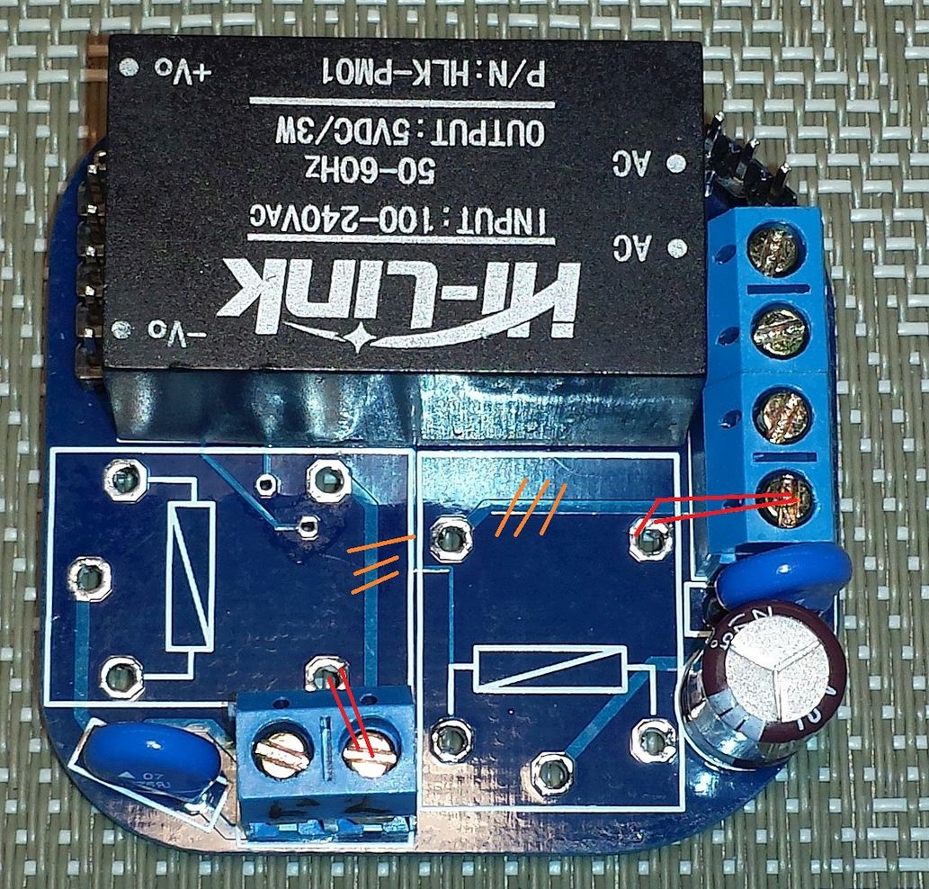
@DDNRN Well, can I cut the lines and rewire the to the NO?
-
Thanks! thats easy.
-
@DDNRN said:
@sweebee said:
@DDNRN Thanks, found it. Ordered one.
Be aware he used NC contacs from the relays! If the ESP fails or has no power your Heating is switched to full throttle all the time!
and
do verify the real outputs with the commands he used > 2x4x1 to switch on the relay but 3x4 gives back 0=on (and 1=off).
Of course I think you will modify the firmware yourself and then its in your handthat can esay change in the aktor.lua at line 139 & 140 change to:
if (gpio.read(pin) == 0) then
c:send(“1”)
ende
if (gpio.read(pin) == 1) then
c:send(“0”)
ende@mwittig thanks for the tipp, now at ebay i have change any, and add new pic’s
@DDNRN yes the next batch of pcb have more copper, and all free gpios get pins
is it okay when only 1 relay change NC/NO ?pic of empty pcb -> http://www.directupload.net/file/d/4234/6jtikduc_jpg.htm
-
@JanGoe said:
@DDNRN yes the next batch of pcb have more copper, and all free gpios get pins
is it okay when only 1 relay change NC/NO ?pic of empty pcb -> http://www.directupload.net/file/d/4234/6jtikduc_jpg.htm
Yes, its OK for me and gives some more flexible functions. Depending on needs you could use failsave NC on one AND failsave NO on the other relais. But I don’t know about others … What about a kind of 3 landing pads with a soldered bridge on users choice?
For a new design I would also reroute some of the small signal wires. Please use as mutch space between this and the Relais routes.
But in general: It’s up to you, it’s your product
-
Hi there!
I am very impressed with Jan’s PCB, so here`s my short tutorial how to add his esp8266-wifi-relay into Pimatic.
The Firmware was written in lua, so i assume that it is known how to upload *.lua’s with ESPlorer.
-
upload all files on the module
-
edit aktor.lua and change rows 1-43 with the following code:
-- pimatic-edition 02.02.2016 version = "0.3.2.pimatic" verriegelung = 0 -- 0 = inaktiv 1=aktiv sid1 = "Licht_Arbeitszimmer" sid2 = "Schlafzimmer_Lampe1" PimaticServer = "192.168.8.200" BaseLoginPimatic = "YWRtaW46YzRqc2luOGQ=" ----------------------------------------------- function send_to_visu(sid, cmd) platform = "Pimatic" if (platform == "Pimatic") then if (cmd == 1) then switch="true" elseif (cmd == 0) then switch="false" end port = 80 link = "/api/device/"..sid.."/changeStateTo?state="..switch.."" end if (platform == "Openhab") then if (cmd == 1) then switch="ON" elseif (cmd == 0) then switch="OFF" end port = 8080 link = "/CMD?" ..sid.."=" ..switch end print(link) conn=net.createConnection(net.TCP, 0) conn:on("receive", function(conn, payload) print(payload) end ) conn:send("GET "..link.." HTTP/1.1\r\n") conn:send("Authorization: Basic "..BaseLoginPimatic.."\r\n") conn:send("Host: "..PimaticServer.."\r\n") conn:send("Content-Type:application/json\r\n") conn:send("Connection: close\r\n") conn:send("Accept: */*\r\n\r\n") conn:on("receive", function(conn, payload) print('Retrieved in '..((tmr.now()-t)/1000)..' milliseconds.\n') --print(payload) conn:close() end) t = tmr.now() conn:connect(port,PimaticServer) end ------------------------------------------------
edit the first line with your pimatic-setup
sid1 – device-id of the first pimatic-switch (relais 1)
sid2 – (if avilable) of the second pimatic-switch (relais 1)
PimaticServer – IP-adress of pimatic
BaseLoginPimatic – Base64-coded string of your “user:passwort” (encode with https://www.base64encode.org/) -
copy the tcp.php from the git-core on your pi (example /home/pi/tcp.php)
sudo wget https://raw.githubusercontent.com/JanGoe/esp8266-wifi-relay/master/tcp.php -
be sure to have php5 installed , if not -->
sudo apt-get install php5 -
now add following code to your pimatic config.json
    "id": "Licht_Arbeitszimmer",
    "name": "Lamp",
    "class": "ShellSwitch",
    "onCommand": "php /home/pi/tcp.php 192.168.8.3 2x4x1",
    "offCommand": "php /home/pi/tcp.php 192.168.8.3 2x4x0",
    "getStateCommand": "echo false",
    "interval": 0
     }
id
must correspond to the respective sidX in aktor.luaname
free to chooseonCommand
command to turn the switch on* php tcp.php 192.168.0.62 2x4x1 command to turn Relais 1 on * php tcp.php 192.168.0.62 2x5x1 command to turn Relais 2 onoffCommand
command to turn the switch off* php tcp.php 192.168.0.62 2x4x0 command to turn Relais 1 off * php tcp.php 192.168.0.62 2x5x0 command to turn Relais 2 offgetStateCommand
command to check the currently switchstate (Pi request --> ESP response)this command you don’t have to use, the ESP sending his currently state to pimatic if the switchstate changes, so “echo false” was okay
interval – interval, how often getStateCommand send Data to ESP (ms)
If all would work you will see in the ESPlorer debug-log by pressing the switch connected on pin GPIO12 and GND
the switch in pimatic should also change for each state.
if change switchstate at pimatic following message appears:
thx for @JanGoe for his compact hardware and @nugged for his help
a german tutorial you will found here
if you need Static IP a temporarily solution found here
(Be sure to set the ESP in Client-Mode first) -
-
Another simple possibility is using MQTT plugin (MQTT Switch). And flash some MQTT compatible firmware. For example ESPEasy.
The advantage is that controlling depends not only on Pimatic.Pimatic = Smart Home
-
hmm… yes… but i think with ESPEasy i cant connect a switch locally on the module and control the on-board relais (offline if my wlan crashes)
-
You can do it. Look at the Device “Level Control”. Looks like you can control the GPIO on the basis of the status of other values. Not only the state of gpio, but also by the analog, temperature, humidity, etc.
I had no time to test it yet properly. I quickly tested pir linked to other GPIO. It works, but I only have the inverse situation.Everything is of course emits over MQTT. It’s even possible to do so and stair switch for example and much more.

Pimatic = Smart Home
-
thanks for the hint
")
i have tried it but they wont work if i will switch in pimatic

did i forget something??
My Pimatic-Device:
    {
      "name": "Beleuchtung WC",
      "id": "switch_wc",
      "class": "MqttSwitch",
      "topic": "/Beleuchtung_WC/gpio/gpio",
      "stateTopic": "/Beleuchtung_WC/switch/switch",
      "onMessage": "1",
      "offMessage": "0"
    },
switch input:

relais output:

locally it works well on ESP, but in pimatic nothing happens
com-output of ESP
Subscribed to: /Beleuchtung_WC/# WD : Uptime 32 ConnectFailures 2 FreeMem 25096 WD : Uptime 33 ConnectFailures 1 FreeMem 25096 SW : State 1 Out : State 0 WD : Uptime 33 ConnectFailures 0 FreeMem 25056 SW : State 0 Out : State 1 -
@xCite86 Try this:
    {
      "name": "Beleuchtung WC",
      "id": "switch_wc",
      "class": "MqttSwitch",
      "topic": "/Beleuchtung_WC/gpio/13",
      "onMessage": "1.00",
      "offMessage": "0.00"
    }
Pimatic = Smart Home
-
thanks… works well with
    {
      "name": "Beleuchtung WC",
      "id": "switch_wc",
      "class": "MqttSwitch",
      "topic": "/Beleuchtung_WC/gpio/13",
      "stateTopic": "/Beleuchtung_WC/switch/switch",
      "onMessage": "1.00",
      "offMessage": "0.00"
    },
so pimatic gets the currently local switch-state also correct…
but if i change the state of the local switch after switching in pimatic nothing happens… it seems to be locked out.
-
as I wrote, untested with pimatic-MQTT
try this:{ "name": "Beleuchtung WC", "id": "switch_wc", "class": "MqttSwitch", "topic": "/Beleuchtung_WC/switch/switch", "onMessage": "1.00", "offMessage": "0.00" }Always switch sends commands to the topic. He listens topic for states. If you use stateTopic, listening on it.
Pimatic = Smart Home
-
Hello,
Thanks @xCite86 for the tutorial,
now version 2 of the pcb is available
new is the pcb have a fuse in front of the HLK-PM01 power supply
and all free gpios have get pinspics at ebay www.ebay.de/itm/322025590037?var=&ssPageName=STRK:MESELX:IT&_trksid=p3984.m1558.l2649
and info at github https://github.com/JanGoe/esp8266-wifi-relay -
@JanGoe
Thx for keep in us up to datepimatic v0.9 has been released!
Support Pimatic and get some free stickers
Like us on Facebookmake it so !
-
now i have 30 pcb’s witch use the NO of the relay