
okay, now looks good wizh 9600Baud, radio init fail, thanks
yes, they should also can handle low currents
hmmm… does the sketch work without NRF?
[TIPS] battery powered sensors
okay, now looks good wizh 9600Baud, radio init fail, thanks
yes, they should also can handle low currents
hmmm… does the sketch work without NRF?
@xCite86 Ah no, the sketch won’t work without a NRF haha. That should be the problem.
ok, tested with following sleepmode-testsketch
#include <avr/sleep.h>
#include <avr/power.h>  //nachladen der benoetigen Bibliotheken
void setup() {
   pinMode(13, OUTPUT);  //definieren von Pin 13 als OUTPUT
   attachInterrupt(0, interrupt, RISING);  //festlegen des Interrupts an Pin 2

}

void loop() {
  digitalWrite(13, HIGH);
  delay(3000);
  digitalWrite(13, LOW);  //3 Sekunden LED leuchten
  enterSleep();  //starten der enterSleep() Funktion
}

void interrupt() {
  //leere Interruptfunktion
}

void enterSleep(){
  set_sleep_mode(SLEEP_MODE_PWR_DOWN);  //festlegen des Schlafmoduses
  sleep_enable();  //ermoeglichen der angegebenen Schlaffunktion
  sleep_mode();  //starten der Schlaffunktion
  //hier geht es nach dem Interrupt weiter
  sleep_disable();  //deaktivieren der Schlaffunktion
  power_all_enable();  //reaktivieren aller Chips/Funktionen
}
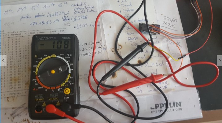
108uA looks good, but you write something about 5uA?
My MySensors Pir’s use around 100-150 uA. But my arduino’s in the all switches uses around 10uA with a 470k pull-up resistor.
Also found this, maybe you can use it as reference:
Unmodified RAW Pin ACT 4.74 mA
Unmodified RAW Pin PDS 0.90 mA
No Power LED RAW Pin ACT 3.90 mA
No Power LED RAW Pin PDS 0.0541 mA*
No Power LED, no Regulator VCC Pin ACT 3.58 mA
No Power LED, no Regulator VCC Pin PDS 0.0045 mA
hey @sweebee
i have build a new relay-device with your 1mhz-pro-mod, remove leds and regulator for a simply battery powered led-nightlight and this sketch.
off-mode --> 0,018A
on-mode with 7 LEDs --> 0,036A
that means only a battery lifetime about 4 days.
was it possible to reduce the power consumption??
the arduino must sleep. If its not sleeping it Will draw to much power. And a arduino with relay is not suitable for batterypower.

70Ah @ 12V, 280Ah@3V hmm… about 226.8333 Days lifetime…

i think i’m looking for 230V lying around in the wall 
I have been trying to flash another bootloader to my 3.3V mini pro’s. I don’t have an UNO to use as programmer so I used a nano. Flashing the nano with the ArduinoISP is no problem at all. Flashing the bootloader via the nano onto the attached pro mini is not possible for me.
I’m using the standard arduino 1.6.5 IDE from Linux.
I looked up a few Google articles about using the nano as programmer and connected everything as described in the articles, with and without a capacitor on the nano between RST and GND. Nothing works. I can’t flash the modded 8MHz 2.4V version and neither the 1MHz version. When flashing (trying to flash) the bootloader I used both the standard “AVR ISP”, the “AVR IPS mkii” and the “Arduino as ISP” setting, but none worked.
In short: Did anyone successfully flash another bootloader onto the pro mini via an arduino nano, and if so: please explain.
Maybe a small supplement for Mac users, who like me couldn’t find the file boards.txt in:
user/library/arduino15/packages/arduino/hardware/avr/1.6.x/
Instead i did the following:
Look for the Arduino app in your application folder, right click on it and select ‘Show Package Contents’.
Then navigate to Contents/Java/hardware/Arduino/AVR. Here you will find the file boards.txt.
You will also find the bootloaders/atmega directory here.
It took we a while to figure this out, so thought i post it here.
Could very well be there’s a much easier solution, but this is what did the trick for me.
Hey @Harry-van-der-Wolf,
did you got your nano working as ISP? I have one of my nanos on a breadboard regulary used as ISP. In case you are still interested I can write a short howto. I often flash my other nanos, but also tried this with a pro mini.
@Anduril said in [TIPS] battery powered sensors:
Hey @Harry-van-der-Wolf,
did you got your nano working as ISP? I have one of my nanos on a breadboard regulary used as ISP. In case you are still interested I can write a short howto. I often flash my other nanos, but also tried this with a pro mini.
I still am not successful in flashing my mini pro’s with a new bootloader (although I must admit I let it rest for the past 1½-2 weeks after coutnless attempts).
So it woud be very nice of you if you could write a short howto.
@Harry-van-der-Wolf as promised, here an explanation of how I burned my bootloader with a nano as ISP.
As I am trying the new MYScontroller and MYSbootloader by tekka I did this quite often and it works reliably.
The following setup:
Nano 1 (used as ISP), Nano 2 (to be programmed)
Just upload the the example from the IDE (examples->11.ArduinoISP->ArduinoISP). I have LEDs connected to pin 7, 8 and 9. The one connected to D9 should be slowly pulsing.
Nano 2 is connected with 5V and GND and 11, 12 and 13 to the respective pins on nano 1. Nano 2 RST to Nano 1 pin 10. I also had to add a cap (1uF) between RST and GND of nano 1.
In the IDE I select the board type and processor entry with the new firmware for nano 2 and the port of nano 1 (which is connected via USB). Than it’s as simple as clicking the burn bootloader button.
A good reading for me when I started flashing was this: http://www.martyncurrey.com/arduino-nano-as-an-isp-programmer/
Maybe it will help you too.
Just to be sure, here a part of my boards.txt which works fine (for fuse settings,…):
##############################################################

nano.name=Arduino Nano

nano.upload.tool=avrdude
nano.upload.protocol=arduino

nano.bootloader.tool=avrdude
nano.bootloader.unlock_bits=0x3F
nano.bootloader.lock_bits=0x0F

nano.build.f_cpu=16000000L
nano.build.board=AVR_NANO
nano.build.core=arduino
nano.build.variant=eightanaloginputs

## Arduino Nano w/ ATmega328 MYSBootloader
## -------------------------
nano.menu.cpu.MYSBLatmega328=ATmega328 MYSBootloader

nano.menu.cpu.MYSBLatmega328.upload.maximum_size=30720
nano.menu.cpu.MYSBLatmega328.upload.maximum_data_size=2048
nano.menu.cpu.MYSBLatmega328.upload.speed=115200

nano.menu.cpu.MYSBLatmega328.bootloader.low_fuses=0xFF
nano.menu.cpu.MYSBLatmega328.bootloader.high_fuses=0xDA
nano.menu.cpu.MYSBLatmega328.bootloader.extended_fuses=0x05
nano.menu.cpu.MYSBLatmega328.bootloader.file=MySensors/MYSBootloaderV13pre.hex

nano.menu.cpu.MYSBLatmega328.build.mcu=atmega328p

## Arduino Nano w/ ATmega328 MYSBootloaderold
## -------------------------
nano.menu.cpu.MYSBLoldatmega328=ATmega328 MYSBootloader old

nano.menu.cpu.MYSBLoldatmega328.upload.maximum_size=30720
nano.menu.cpu.MYSBLoldatmega328.upload.maximum_data_size=2048
nano.menu.cpu.MYSBLoldatmega328.upload.speed=115200

nano.menu.cpu.MYSBLoldatmega328.bootloader.low_fuses=0xFF
nano.menu.cpu.MYSBLoldatmega328.bootloader.high_fuses=0xDA
nano.menu.cpu.MYSBLoldatmega328.bootloader.extended_fuses=0x05
nano.menu.cpu.MYSBLoldatmega328.bootloader.file=MySensors/MYSBootloader.hex

nano.menu.cpu.MYSBLoldatmega328.build.mcu=atmega328p

##############################################################

pro.name=Arduino Pro or Pro Mini

pro.upload.tool=avrdude
pro.upload.protocol=arduino

pro.bootloader.tool=avrdude
pro.bootloader.unlock_bits=0x3F
pro.bootloader.lock_bits=0x0F

pro.build.board=AVR_PRO
pro.build.core=arduino
pro.build.variant=eightanaloginputs

{...}

## Arduino Pro or Pro Mini (3.3V, 1 MHz, MYS Bootloader) w/ ATmega328
## --------------------------------------------------
pro.menu.cpu.1MHzatmega328=ATmega328 1 MHz MYS Bootloader

pro.menu.cpu.1MHzatmega328.upload.maximum_size=30720
pro.menu.cpu.1MHzatmega328.upload.maximum_data_size=2048
pro.menu.cpu.1MHzatmega328.upload.speed=57600

pro.menu.cpu.1MHzatmega328.bootloader.low_fuses=0x62
pro.menu.cpu.1MHzatmega328.bootloader.high_fuses=0xD8
pro.menu.cpu.1MHzatmega328.bootloader.extended_fuses=0x06
pro.menu.cpu.1MHzatmega328.bootloader.file=MySensors/MYSBootloader.hex

pro.menu.cpu.1MHzatmega328.build.mcu=atmega328p
pro.menu.cpu.1MHzatmega328.build.f_cpu=1000000L
@Anduril : Thanks.
However, your example describes how to program a nano via another nano as ISP. I did that and that is not a problem.
My problem is to bootloader flash a pro mini via a nano.
I tried it via a couple of wiki howto’s from the web from nano2mini-pro.
I also followed the one you link to, and others for nano2nano (for the mini). I tried the ones from Uno2mini-pro and from Uno2nano (for the mini).
And yes: I also tried a real nano2nano and that worked flawless. Using both nanos (not at the same time of course) to bootloader flash a mini-pro didn’t work either.
Slightly different configs to use a nano to simply flash a program (ino) to a mini-pro do work. Only the bootloader flashing doesn’t work. I always get communication errors.
It would have been nice if this worked, but I don’t care that much anymore. I have a 3.3V 8MHz mini pro without leds and power regulator and after 4-5 months it is at 58%. I can live with that ")
@Harry-van-der-Wolf I also did the same process with a pro mini, no difference. Connect 11<->11, 12<->12, 13<->13 and 10(ISP)<->RST(to be flashed) and GND and 3V3 if using a 3V3 pro mini. I have one pro mini running with the settings written above, MYS bottloader and 1Mhz clock speed.
@Harry-van-der-Wolf one thing to think about is your sleep/awake time quotient. In case your node is mostly sleeping, the change of some mA for milliseconds while sleeping 10 minutes will not make a difference. And your node will need more time to run the sketch. It is very difficult to realy say what is better: little bit higher consumtion but faster measurement, or slower and less power hungry.
Only point for me to burn new bootloader and fuses was to set BOD level and to have a bootloader with OTA upload.
But to come back to your problem: I will prepare a spare pro mini I have lying around and repeat with that. I will report back and maybe can give you some further help.
Is it a problem to burn the bootloader with the radio already attached?
yes its a problem, if you programm the Arduino over ISP. ISP is the same interface as radio is connected.
Pimatic 0.9 i love it!
Did anyone get the 1MHz version working with a DHT22? I’ve tried different libraries but all fail.
Hi all,
Somehow I have the feeling i’m doing something wrong. I have done all off the above and it seems everything is working but if i measure the power consumption of only my Pro Mini (3.3V) i have a 650uA, when i connect a motion sensor and 2.4 GHz radio (via Mysensors). I go to 300mA. Can somebody help me to solve this issue?
@TVN said in [TIPS] battery powered sensors:
Hi all,
Somehow I have the feeling i’m doing something wrong. I have done all off the above and it seems everything is working but if i measure the power consumption of only my Pro Mini (3.3V) i have a 650uA, when i connect a motion sensor and 2.4 GHz radio (via Mysensors). I go to 300mA. Can somebody help me to solve this issue?
I actually mean 3.5mA. My bad.
