I don´t know why but after updating the code of the sensor node the voltage measuring works.
I will check it but I hope it works further.
[TIPS] battery powered sensors
I don´t know why but after updating the code of the sensor node the voltage measuring works.
I will check it but I hope it works further.
Did anyone tried some low voltage PIRs in comparison to the standard HC-SR501?
The voltage range is from 0.8 to 9V. Current the same, about 50uA.
@Heizelmann i use this one and they work very well. the only thing is … there is no variable resistor to change the sensitivity and hold time
pimatic + MySensors + Homeduino + z-way
https://github.com/n3roGit/MySensors_n3ro
Thanks for the great tutorial @sweebee . I was finally able to flash the arduino with the boot loader. Besides I was able to get debug output but had to set the baud rate to 9600. 4800 could work even better
@sweebee :
I just got my set of mini pro’s delivered. Of course I want to move on to the low-power mods but I have one (maybe stupid) question:
Once the regulator is removed you type in the first post:
“Remove the components according to the image below (please do not cut any lines, removing the components will do it). After that you can’t use the Vcc of the programmer anymore.”
Can I still flash my pro mini afterwards? Or should I flash first with the definitive version and then remove the regulator?
@Harry-van-der-Wolf you can stil program it after removing that components. Only the RAW input won’t work, but that’s not needed ofc with battery powered sensors.
@sweebee maybe a stupid question, but how do you get the 1mhz bootloader on your pro mini’s without the headers soldered (like in his picture)?
@lxz before soldering the nrf shield, just plug in some wires to pin 11,12,13,reset, gnd and vcc. Hold it tight so they are connected correctly and upload the bootloader.
Ok, too easy ")
I have uploaded the bootloader for the 1 Mhz version with my USBASP. However now I am testing it to upload the program blink but I can not upload it to the pro mini. Any idea’s?
I had the same problem last week and when using a different pro mini it worked.
I think it has to do with the baud rate of the serial port and the tolerance of the crystal. The difference is too much and no valid characters are received. Same as when strange characters appear during debugging.
Btw you can’t use the isp to upload the blink sketch. I assume you use the boot loader of the pro mini for this? So over the serial port?
@rikki78 I have used the usbasp for uploading the bootloader. Uploading the blink was via the FTDI. I will try another pro mini. Is there any way to reduce the baud rate when programming via the FTDI?
@dynamite by default its 9600, can’t be set lower unless you find a different bootloader with a lower baudrate.
got my Pro-Mini’s today and can say a little bit about power-consume while running in active mode with following loop-sketch
void setup() {
  pinMode(13, OUTPUT);
}

void loop() {
  digitalWrite(13, HIGH);
  delay(10000);
  digitalWrite(13, LOW);
  delay(10000);
}
first setup, unmodified
second setup, removed PowerLED
third setup, removed PowerLED, removed VoltageRegulator
fourth setup, removed PowerLED, removed VoltageRegulator, 1mHz-Mod
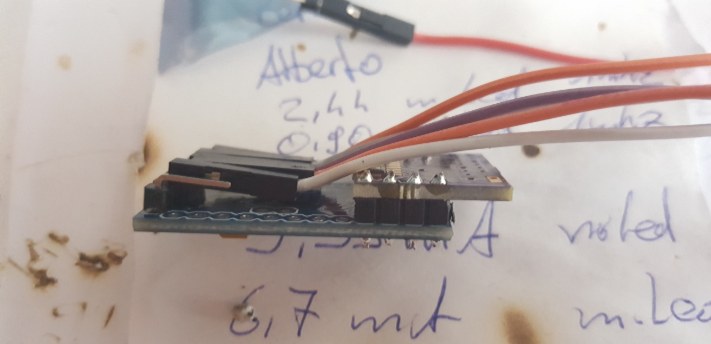
first soldering looks good

@xCite86 how did you solder that shields? Not directly on the pro mini? I just soldered then without any headers.
Measured the consumption in sleep mode already? That should give around 5uA.
no, not direct, i use the header
hmm… no, i have ~0,8mA in sleep mode, maybe i do something wrong? but following code should do something about 5 seconds after bootup and then go to sleep.
#include <MySensor.h>
#include <SPI.h>
#include <Bounce2.h>

#define CHILD_ID 4
#define BUTTON_PIN  8  // Arduino Digital I/O pin for button/reed switch

MySensor gw;
Bounce debouncer = Bounce();
int oldValue=-1;

// Change to V_LIGHT if you use S_LIGHT in presentation below
MyMessage msg(CHILD_ID,V_TRIPPED);

void setup()
{
  gw.begin();

 // Setup the button
  pinMode(BUTTON_PIN,INPUT);
  pinMode(6, OUTPUT); // Power Pin for A/D Module
  // Activate internal pull-up
  digitalWrite(BUTTON_PIN,LOW);

  // After setting up the button, setup debouncer
  debouncer.attach(BUTTON_PIN);
  debouncer.interval(5);

  // Register binary input sensor to gw (they will be created as child devices)
  // You can use S_DOOR, S_MOTION or S_LIGHT here depending on your usage.
  // If S_LIGHT is used, remember to update variable type you send in. See "msg" above.
  gw.present(CHILD_ID, S_DOOR);
}


//  Check if digital input has changed and send in new value
void loop()
{
  digitalWrite(6, HIGH); // Power on YL-38 A/D Module
  delay(2000);
  debouncer.update();
  // Get the update value
  int value = debouncer.read();

  if (value != oldValue) {
     // Send in the new value
     gw.send(msg.set(value==LOW ? 1 : 0));
     oldValue = value;
  }
  delay(2000);
  digitalWrite(6, LOW); // Power off YL-38 A/D Module
  gw.sleep(3600000); // wait a hour, then reloop
}

btw, the serial output shows me only a ÿon 9600 Baud, ²¡¤©¯€©®©´€¦¡©¬Š on 115200 Baud
@xCite86 yes most of the time the 1mhz bootloader can’t handle baudrates that high. If your using the MySensors sketches you have to lower the baudrate in MyConfig.h in the MySensors library folder. Set it to 9600 or so.
870 uA is way to high. Can your meter handle low uA’s?
okay, now looks good wizh 9600Baud, radio init fail, thanks
yes, they should also can handle low currents
hmmm… does the sketch work without NRF?
@xCite86 Ah no, the sketch won’t work without a NRF haha. That should be the problem.
ok, tested with following sleepmode-testsketch
#include <avr/sleep.h>
#include <avr/power.h>  //nachladen der benoetigen Bibliotheken
void setup() {
   pinMode(13, OUTPUT);  //definieren von Pin 13 als OUTPUT
   attachInterrupt(0, interrupt, RISING);  //festlegen des Interrupts an Pin 2

}

void loop() {
  digitalWrite(13, HIGH);
  delay(3000);
  digitalWrite(13, LOW);  //3 Sekunden LED leuchten
  enterSleep();  //starten der enterSleep() Funktion
}

void interrupt() {
  //leere Interruptfunktion
}

void enterSleep(){
  set_sleep_mode(SLEEP_MODE_PWR_DOWN);  //festlegen des Schlafmoduses
  sleep_enable();  //ermoeglichen der angegebenen Schlaffunktion
  sleep_mode();  //starten der Schlaffunktion
  //hier geht es nach dem Interrupt weiter
  sleep_disable();  //deaktivieren der Schlaffunktion
  power_all_enable();  //reaktivieren aller Chips/Funktionen
}
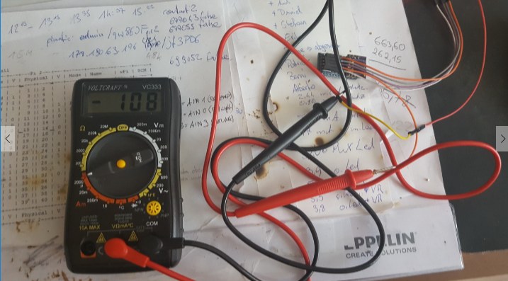
108uA looks good, but you write something about 5uA?