Hi, I have a problem with a WS2812 / WS2812b LED ring. I bought this ring here ex-Store
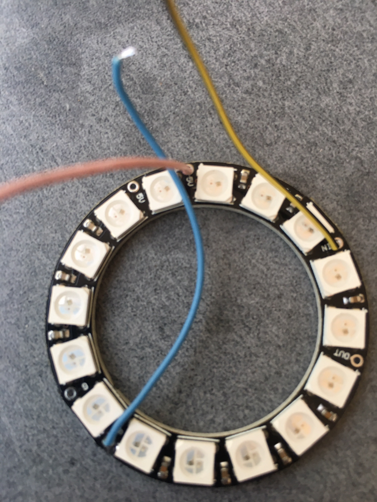
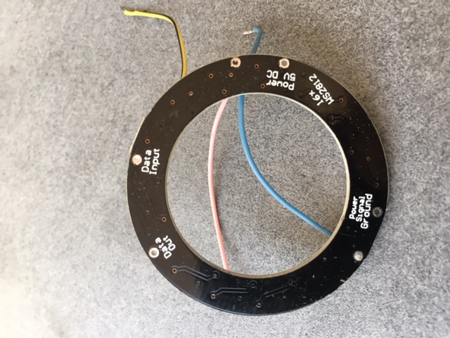
On pictures it seems to be identical with these rings: Reichelt and Eckstein. Although these rings are from Adafruit. Mine’s a Chinese replica, probably. I think it should be the same as a WS2812b strip. But it doesn’t work.
I already have some WS2812b running, e.g. my HomeStatusDisplay has been running 24/7 for about a year.
But I can’t get this ring to glow.
As a control module I use a Wemos Mini, with a safety circuit of Led studies .
On the wemos I installed tasmota 6.5.0 Classic. The structure is identical to my structure of the HomeStatusDisplay.
The seller was so kind to send me a second ring.
But also the second LED ring does not light up. No matter what I do.
Does anyone have experience with such a LED ring? Can anyone tell me what I am doing wrong?
-
WS2812 / WS2812b Ring does not want to light up | Or differences between Wemos D1 Mini and NodeMCU
"Really, I'm not out to destroy Microsoft. That will just be a completely unintentional side effect." 09-28-2003, LINUS TORVALDS (http://www.nytimes.com)
-
After trying and trying something different with a few pauses, I have obviously come to a cause of the problem.
As already written I used a Wemos D1mini as controller. Now I made a test setup with NodeMCU. And suddenly the LEDs come to life.
So there seem to be differences between wemos and NodeMCU. But NodeMCU has an earlier version of Tasmota, that runs 6.4.1, should that be the reason? In the change log I cannot find any changes to the WS2812 protocol or library.
The Wemos has smaller dimensions than NodeMCU. Therefore I cannot use NodeMCU. Can someone tell me what I have to do to get the Wemos to work with the WS2812 LEDs?"Really, I'm not out to destroy Microsoft. That will just be a completely unintentional side effect." 09-28-2003, LINUS TORVALDS (http://www.nytimes.com)
-
Strangely enough, the images on the Oscilloscope look very similar. The first of the NodeMCU, the second Wemos, with the same settings.
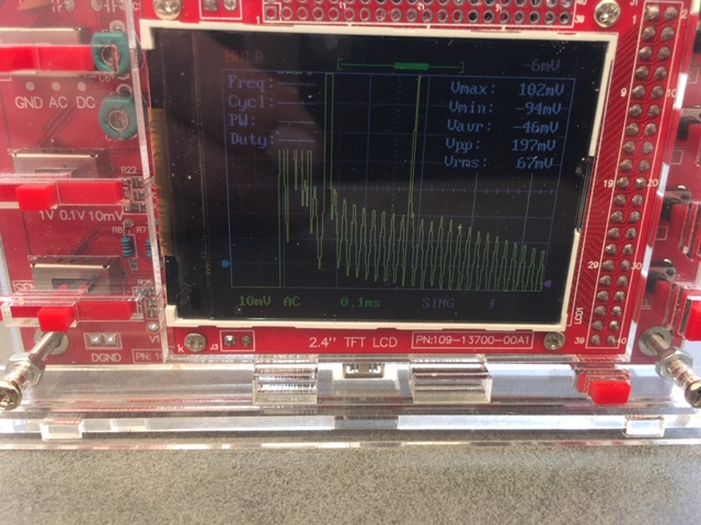
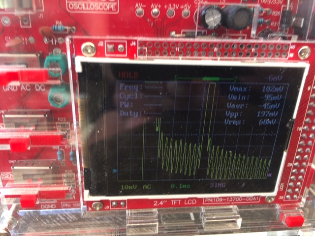
But something has to be different. Because the LED ring on the Wemos doesn’t light up.
"Really, I'm not out to destroy Microsoft. That will just be a completely unintentional side effect." 09-28-2003, LINUS TORVALDS (http://www.nytimes.com)
-
I need to correct something there. After I tried to measure the output of the data line to the WS2812 with the Oscilloscope, I noticed that the ring works. A few other attempts and the ring didn’t work again. Until I finally found out that the ring works when I have attached the Oscilloscope terminals. The device seems to bring a required potential to the data line. Although the oscilloscope has a different power source. Unfortunately I don’t know enough about the electronics. I also don’t know how to measure this potential. Can someone give me a hint? Should I put a pull-up or pull-down resistor on the data GPIO? And what value should it have? Currently I have a 330Ohm resistor between GPIO and WS2812 to protect the first LED and a 470µF electrolytic capacitor in front of the Wemos between VCC and GND.
"Really, I'm not out to destroy Microsoft. That will just be a completely unintentional side effect." 09-28-2003, LINUS TORVALDS (http://www.nytimes.com)
-
Is gnd of the LED Ring connected with wemos/nodemcu gnd?
-
Yes, of course. Without GND nothing would work, I think.
Next I will remove the 470µF electrolytic capacitor from the Wemos. But only tomorrow or the day after tomorrow, let’s see how the weather develops 😉.
The NodeMCU currently has no support capacitor, because I only use it for testing.
But the Wemos should run 24/7, so I thought the capacitor is necessary for a stable run."Really, I'm not out to destroy Microsoft. That will just be a completely unintentional side effect." 09-28-2003, LINUS TORVALDS (http://www.nytimes.com)

