@Azrael
The broker (mosquito) is the server that receives and distributes everything. It can be installed besides pimatic on the raspberry (localhost). But it can also run on another system (e.g. NAS, second raspberry). The pimatic plugin works as client, as well as the tasmota devices.
-
Pimatic mit ESP8266 - NodeMCU oder ESP-01
-
On the sonoff/tasmota website go to “Configuration”. Then click on “Configure mqtt”. Here you can enter the IP of your mosquitto at Host.
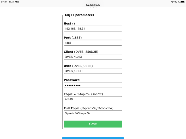
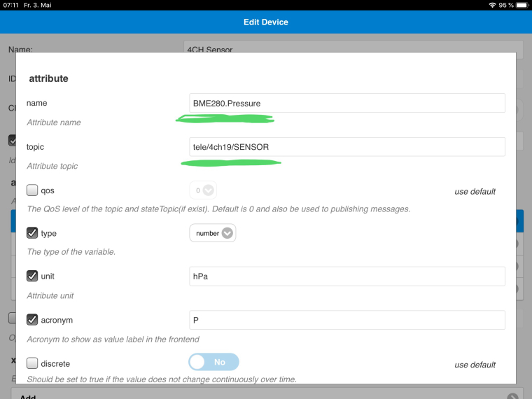
Port 1883 is default. Below you can see the topic.
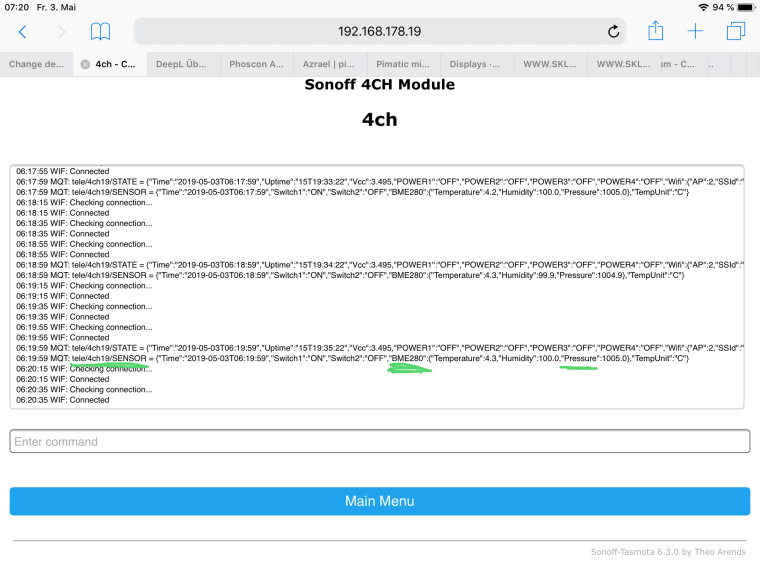
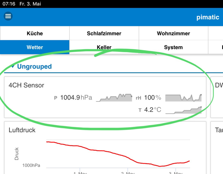
On the first page there is a button “Console”. Here tasmota shows you all messages you want to see. Here it also shows you the Topic’s you need.
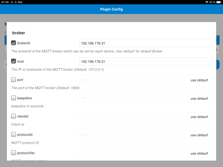
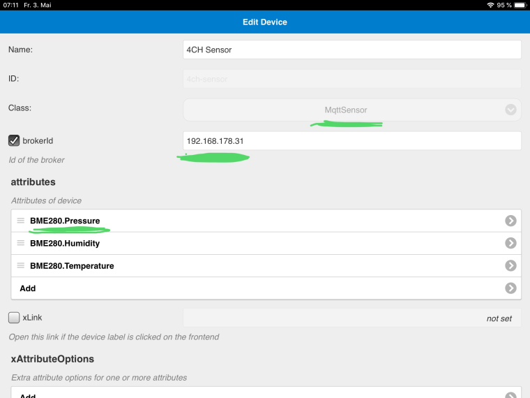
In pimatic it looks like this:
In the mqtt plugin settings of pimatic the IP of mosquitto must be set. And a restart of pimatic is then necessary.
-
Hello, everyone,
Thanks a lot! That was exactly what I was missing. I didn’t know how important the names were in the MQTT. Therefore my sensors were not recognized.
Maybe you can help me with how I can now use the NodeMCU via MQTT to send a 433MHz transmitter of this kind https://www.amazon.de/gp/product/B071J2Z3YK/ref=ppx_yo_dt_b_asin_title_o08_s00?ie=UTF8&psc=1
Can I talk to this one to be able to switch various radio sockets away from the RPi?Translated with www.DeepL.com/Translator
-
@azrael
I’m afraid I’m out of it. But there are some projects with NodeMCU or Wemos and mqtt.
Zb hereOn the other hand, if your distance from the RPi to the RF sockets isn’t too great, why do you want to take the detour via mqtt? You could use the pimatic homeduino plugin.
I have Homeduino transmitting up to about 10m. Through a few walls and a ceiling. My roller shutters open and close regularly. Quite rarely the time a signal gets lost. The disadvantage is that there is no feedback at 433mHz. You have to live with it.
Here is a very good description of @leader21.
-
Thanks, I’ll take a look at that article.
Currently I have connected a 433MHz transmitter directly to the RPi via breakout board. This controls a terrarium in my living room.
I have another terrarium on the completely other side of the apartment (5 walls and about 20 meters away). There I installed now an ESP which gives me the temperature data of the terrarium and the environment. But also at this terrarium one or the other would have to be switched, this would have to run via WLAN, therefore the NodeMCU.
Furthermore I have a 3rd terrarium in my basement, which I would like to measure and control via NodeMCU as well. In addition to the 5 walls and 20 meters there are 3 floors (ceiling).Homeduino I must also still look at, with this I would like to replace the Breakout Board. But this is further back on the ToDo list. This has less to do with necessity than with appearance and comfort
") .
. -
@azrael
Why don’t you work with a relay board directly on NodeMCU. They come with one, two, four, and more relays. This would give you a safe feedback.
Or do you want to build a “Wifi extension” with Rf 433mHz?
A Wemos as a repeater would also be a possibility.
There is also another ESP, e.g. ESP8266-01. The Wemos or NodeMCU has the advantage that the periphery is already given. You can power them directly with a USB cable. -
@Thrusty
I didn’t want to use the relay board because I have to connect 230V completely and I don’t think these relays without housing are completely harmless, especially if there are children in the house.
There is the possibility to switch radio sockets per 433MHz but the safer one. Since all live parts are then also cleanly processed.What do you mean with a repeater via Wemos? So single stations with 433MHz receiver and transmitter to carry the signal? I think this is very susceptible to interference, or have you had other experiences?
I found the power supply of the NodeMCU via Micro USB quite good. They provide enough power for the sensors and the 433MHz transmitters. I wanted to solder it all and install it in a surface mounted junction box.The MQTT sensor query of the 3 nodes is spinning around since this morning and I can’t do anything with the error. At the same time Pimatic shows the following error:
error [pimatic]: Error loading device “nmcu3”: (@plugin.brokers[@config.brokerId])
error [pimatic]: Error loading device “nmcu2”: (@plugin.brokers[@config.brokerId])
error [pimatic]: Error loading device “nmcu1-temp-tiefland”: (@plugin.brokers[@config.brokerId])A restart of Mosquitto, Pimatic and finally the whole Pi didn’t make any difference.
The error occurred at 11:27 this morning. The last 2 days, however, no changes were made at the configuration. -
This post is deleted!
-
@azrael
The one with the 230V is of course true. You have to tinker a little bit more to pack it safely.The one with the repeaters is actually not quite right. Strictly speaking you can also call it a router (NAT). But I’m still testing it myself. It doesn’t really work yet, not as I thought.
And your error, I can only google such things. But take a look at this maybe it helps. Or maybe this. I had a similar mistake once, or the same mistake!? 🤔
-
At the start of pimatic i also used a lot of 433 mhz divices, but they arent realy reliable, so i only use esp divices now with ESPEasy.
Here you can find some infos, maybe it helps:
https://forum.pimatic.org/topic/1367/espeasy-with-pimatic-over-mqttHabe früher auch nur 433 mhz Geräte benutzt, allerdings kann man sich nie sicher sein, ob diese auch wirklich schalten. Deswegen nutze ich auch nur noch ESPEasy.
-
@Azrael
@4nubis said in Pimatic mit ESP8266 - NodeMCU oder ESP-01:At the start of pimatic i also used a lot of 433 mhz divices, but they arent realy reliable, so i only use esp divices now with ESPEasy.
Here you can find some infos, maybe it helps:
https://forum.pimatic.org/topic/1367/espeasy-with-pimatic-over-mqttHabe früher auch nur 433 mhz Geräte benutzt, allerdings kann man sich nie sicher sein, ob diese auch wirklich schalten. Deswegen nutze ich auch nur noch ESPEasy.
That’s what I’m talking about.
-
Sorry the last days I missed the time for the project. Now I want to go on
@4nubis
How do you switch your devices with ESPEasy? I’ve flashed a NodeMCU with it but I’m quite unaware how I can switch the devices better than with Tasmota.
433MHz doesn’t seem to be possible with it either. What is the alternative in this case? Also with relay?@Thrusty
You switch your devices completely with relays despite less “protection”?Translated with www.DeepL.com/Translator
Sorry die letzten Tage hat mir leider die Zeit für das Projekt gefehlt. Nun soll es dann mal weitergehen
@4nubis
Wie schaltest Du Deine Geräte mit ESPEasy? Ich hab nun mal eine NodeMCU damit geflasht bin aber doch recht Ahnungslos wie ich damit die Geräte besser schalten kann als mit Tasmota.
433MHz scheint auch damit nicht ohne weiteres möglich zu sein. Wie ist in dem Fall die Alternative? Auch mit Relais?@Thrusty
Du schaltest Deine Geräte trotz weniger “Schutz” komplett mit Relais? -
@azrael
I only have one ESP-01 with an open relay, both in a box.Otherwise I use any Sonoff Pow‘s, Sonoff Basic‘s and Sonoff 4CH‘s. The first two are already closed. The 4CH’s sits on a DIN rail, in the switch box.
And a Shelly, there is in a flush-mounted box. -
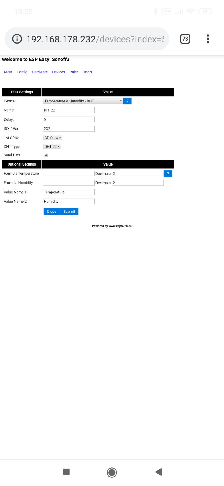
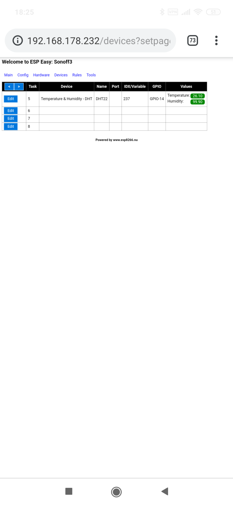
Which one of you still uses ESP Easy? I don’t get any sensor data from DHT22 on my ESP Easy flashed NodeMCU.
The structure of the NodeMCU is the same as the previously flashed Tasmota.
The sensor is configured to D3 (GPIO-0), but does not display any data under Devices. Does anyone have an idea what this could be?Wer von euch nutzt denn noch ESP Easy? Ich bekomme auf meinem ESP Easy geflashten NodeMCU keine Sensordaten vom DHT22 abgefragt.
Der Aufbau des NodeMCU ist gleich geblieben zu dem vorher geflashten Tasmota.
Der Sensor ist auf D3 (GPIO-0) konfiguriert, Zeigt aber unter Devices keine Daten an. Hat jemand eine Idee an was das liegen kann? -
-
Hey, sorry das ich mich so lange nicht gemeldet hab. Die letzten Tage waren sehr stressig.
@4nubis
Danke für die Screenshots. Mit diesen Einstellungen funktioniert es. Woher bekommt man denn die Einstellungen für “IDX/Var” bzw. wodurch ergibt sich der Wert?
Und welche dieser Werte:1802868875 : DHT : Temperature: 24.70
1802868875 : DHT : Humidity: 62.60Frage ich denn davon nun in Pimatic ab?
Einige von euch verwenden mit Pimatic und MQTT offenbar um Relais zu schalten nutzt ihr dafür die “normalen” Relais wie z.B. diese hier?
https://www.amazon.de/gp/product/B07LB2RQYP/ref=ppx_yo_dt_b_search_asin_image?ie=UTF8&psc=1
Oder nutzt ihr andere um 230V sicher schalten zu können?Viele Grüße
Azrael
Hey, sorry I haven’t contacted you in so long. The last days were very stressful.
@4nubis
Thanks for the screenshots. With these settings it works. Where do I get the settings for “IDX/Var” or what is the value?
And which of these values:1802868875 : DHT : Temperature: 24.70
1802868875 : DHT : Humidity: 62.60Do I ask about it now in Pimatic?
Some of you use with Pimatic and MQTT apparently to switch relays you use the “normal” relays like this one?
https://www.amazon.de/gp/product/B07LB2RQYP/ref=ppx_yo_dt_b_search_asin_image?ie=UTF8&psc=1
Or do you use others to switch 230V safely?Many greetings
AzraelTranslated with www.DeepL.com/Translator
-
Hello,
I’m just using tasmota right now. I have tried Espeasy. I had it on a NodeMCU for some time to control a display with ws2812. Unfortunately some of the LEDs flash uncontrolled. Maybe the problem was not EspEasy. I’ve made some changes to the circuit since then. Now the display works without problems with tasmota 6.5. Otherwise I have tasmota on all devices, from version 5.11 to 6.5.
On about 10 devices. The handling is the same everywhere. I find it easier this way.
As long as I don’t need any of the sensors that espeasy supports, I will probably stay with tasmota. Furthermore, I have a quick overview of all devices with the tasmota device manager (TDM) . The TDM even shows devices that are in the subnetwork.