Having digged a little deeper, I don’t think the potential free switching will work in this context. I think @V1per 's suggestion (the drawing in post 11) should do the trick and logically it is parallel switch. You must be careful with the cabling, however.
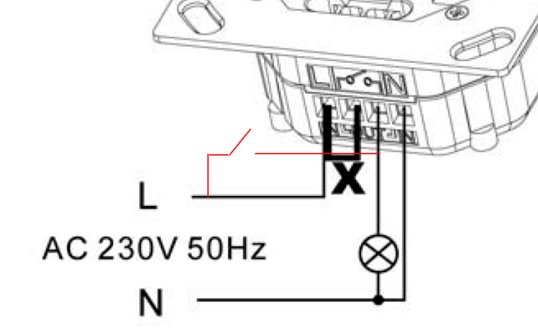
Here is another drawing. The red line ist the cabling for the mechanical switch. The wire bridge X is kept in as is.
Besides this ITLM-1000 appears to be the better choice for your setting and on/off siwtch but it lacks the other features like the timer and the potential free switching option.
In the wall closet you should have two blue wires and one black wire, but quiet often it is somewhat different and you’ll need to check which has phase anyway. On one cable (blue) you should have the phase. This needs to be mounted to L of the terminal. The other blue cable (no phase) is mounted to “switch out” (the third pin from the left) of the terminal. The black cable N (no phase) is mounted to N. Now you need two cables to mount you mechanical switch. If possible mount them to L and “switch out” of the terminal.
"It always takes longer than you expect, even when you take into account Hofstadter's Law.", Hofstadter's Law


") In my case the live (L) wire was the black one and the neutral (N) one was blue. It’s always good to expect the unexpected
In my case the live (L) wire was the black one and the neutral (N) one was blue. It’s always good to expect the unexpected 