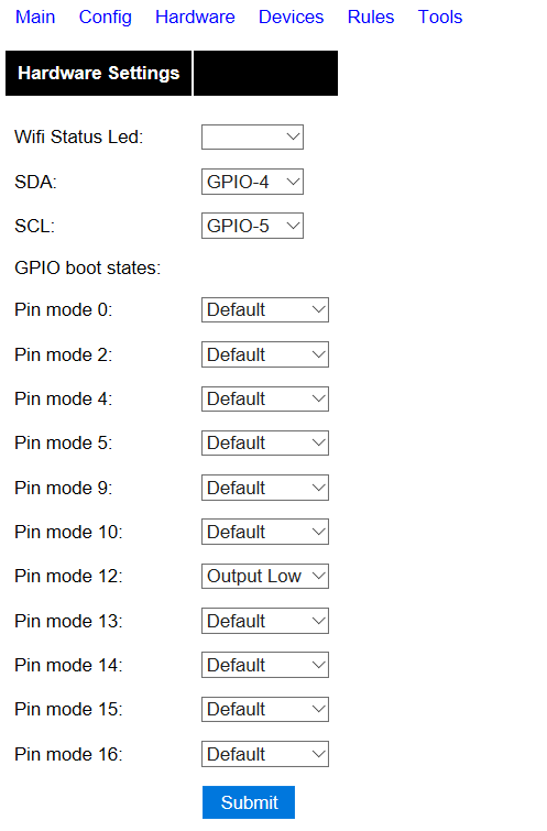
@Harry-van-der-Wolf I use the same commands to set the state of the switches. Because it is setting the gpio directly you have to use 0 for on and 1 for off. If you use the rest API you can get the status of the switch sent back to Pimatic. Make sure the name of the switch in Espeasy and Pimatic is the same. One feature of Espeasy is that you can give a boot state to the switch. Important for a thermostat. You can find this under hardware. Here you can give a low or high state. If you do not mark it as inversed use high otherwise low. Another feature you can find under tools advanced. Connection failure threshold. If the ESP looses connection it will reset and if you have set the bootstate the thermostat will be in the off position (safe position). Important because in case of Pimatic or wifi problems you have to stop the heater. The room temperature I measure with a mysensors temperature sensor (battery powered). If this one is not updated every 5 minutes it also turns of the heater.
As @wutu said you do not have to mark it as inversed but for easy understanding if you also have normal operating switches (sonoff) it is better to inverse them.
-
relay with espimatic or EspEasy
-
@jopiek Thanks for your extensive answer.
However, @wutu mentioned that I don’t need a switch device at all, especially not as it is an input switch (as far as I understood from his answer).
Based on your first post I assume you have configured the input switch, just like I did.
Like:
IDX => some number (above screen capture mentions 0, but I had 245. However, I thought this was only for Domoticz)
Pull Up: checked (or not?)
Inversed: checked
Switch type: Switch
Send boot state: ?? (I thought this was not to set the boot state, but to send the boot state. So to simply send the state it is in upon (re)boot)(The reason I’m doing is is because the espimatic was again 1 hour offline this morning and then suddenly reappeared. Beats me)
-
@Harry-van-der-Wolf IDX does not matter for Pimatic only for Domoticz. Can be anything except 0 I believe
Yes send the boot state means it will send its state to Pimatic. Setting the boot state you will do in the hardware screen.
Maybe a stupid question but what kind of power supply do you use for the ESP?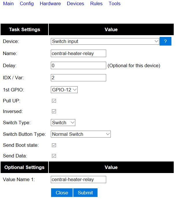
-
Thanks for your answer. I misunderstood your boot state answer.
I do use a good “certified” 2A power supply, not a cheap one. I don’t know which brand.
Tonight the next session to get the EspEasy running.
")
-
@Harry-van-der-Wolf You can also switch the state during query:
curl http://<ESP IP address>/control?cmd=status,gpio,5 | grep state | awk {'print $2'} | if [ $? == 0 ]; then echo "1"; else echo "0"; fiPimatic = Smart Home
-
@Harry-van-der-Wolf 2A should be sufficient but be aware there are many differences between the micro USB cables. The cheap ones from Action for example do not even give 0.5A and can cause strange behaviour. If it is only a relay and temperature sensors that you need Itead has some nice solutions for it with the sonoff devices. Only need to solder 4 pins on them and replace the firmware with Espeasy. Afterwards the firmware can be updated OTA.
-
What you are/were essentially trying to do is use GPIO 12 both as input AND output at the same time, which will give you (obviously) a hard time.
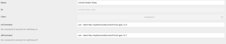
If you just want to activate(/deactivate) the relay from ESPEasy, you just need to set the output of the corresponding pin (gpio 12) to 0 (most relay boards need the pin to be pulled to ground to enable). Example via http: http://ipadress-ESP/control?cmd=GPIO,12,0 or MQTT: send a message to topic /ESPEasy_name/gpio/12 with value 0 (or 1 to disable the relay).If you want to wire up a hardware switch to the ESP to be able to swich the relay as well, that is also possible, but then you will need to use another pin, define it as a switch input and use the rules to switch on/off the relay.
-
@Rene-Arts it is only a relay output not an input and it works very well. Description in Espeasy is confusing.
-
@jopiek It might be just me, but I don’t get what is confusing about it. There essentially is nothing to configure when you want to hook up a relay. Just hook it up and set the corresponding (output) pin to 0 or 1. Only when you want to define the pin state right after (re)booting you need to select “output low/high” in the hardware tab. Nothing more to it
")
-
I have continued my experiments with the relay on the Esp Easy.
It is not neccessary indeed to define a device. Simply setting the status to On or off is sufficient, also to get the status.
No inverse or whatever is needed either. This is of course also dependent on how you connect the relay. The keyes relay is an active low relay (I’m still not absolutely sure what that means. I’m not so “electrically developed”).
As I’m not so electronically savvy, I type down what I did (maybe there are others like me )
I have connected it this way:

See the unconnected relay 2 for what the open/closed connections are.
If I connect the relay like this on the 2nd (center) and 3rd (right) connection, I don’t need to reverse the signal.
If I connect the wires to the 1st (left) and 2nd (center), I do need to reverse the signal.
So when connected like this, e.g. 2 and 3, a gpio=0 means no heating, and a gpio=1 will heat up.However, there seems to be one regression error in the Esp Easy (my version is R139). When you don’t set a boot state to the relay, you can’t request the status after reboot. It is as if the relay is “state less” for the EspEasy software: it hasn’t got a clue about the state. Once you give it a state, no matter on or off which does or does not trigger a switch state, EspEasy seems to know the switch state and this switch state can be requested.
If you do set a state during boot EspEasy knows the state and this state can be requested immediately after reboot (or cold boot). -
@Harry-van-der-Wolf said in relay with espimatic or EspEasy:
I have continued my experiments with the relay on the Esp Easy.
It is not neccessary indeed to define a device. Simply setting the status to On or off is sufficient, also to get the status.
No inverse or whatever is needed either. This is of course also dependent on how you connect the relay. The keyes relay is an active low relay (I’m still not absolutely sure what that means. I’m not so “electrically developed”).Let me try to educate you (and others) a bit, never too late to learn, right? I’ll try to keep it simple, feel free to ask for clarifications or questions!
This is one of the most used schematics for relays, I strongly suspect it is identical to yours.
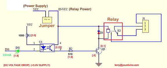
The ESP is hooked up to VCC, GND and one of the GPIOs to IN0.
U1 is an optocoupler, which is a light emitting diode and a transistor in one package. Some basic information: every transistor is sensitive to light, but mostly we use a transistor in its own housing, keeping away all outside light from the silicon, yielding it only sensitive to electric potential or current. (Raspberry Pi 2 suffered from a housing of a voltage regulator which was not shielding light --> flash gate was born).
When IN0 is pulled to ground (by the ESP) there will be a voltage across R1 and the LED in the optocoupler, causing the led to illuminate the silicon in the transistor.
The transistor in its turn will start to conduct (turn on), causing a current running through the base and emitter of transistor Q1, which turns on as well. Then finally the current running through Q1 and the solenoid (depicted as the small square) of the relay causes the contacts of the relay K1 to switch from the normally closed (pin 2 and 3 connected) to the normally open (pin 1 and 2 connected) position.So if IN0 is driven high, there is no current running through the LED in U1, the transistor stays closed, transistor Q1 stays closed and the relay stays closed (and pin 2 and 3 are connected).
I hope by now the active-low seems a bit more logical: if the input is pulled low, the relay is switched on (normally-open pin 1 and 2 are now connected).
One of the advantages of this setup is the optocoupler: there is no direct electrical connection between the GPIO pin and the relay or its load, thus providing galvanic isolation. This provides a bit of extra safety, reliability and immunity to noise signals from the high voltage side. I need to add though that this only holds when the jumper is open and VCC and JD-VCC are separate power supplies.
-
@Harry-van-der-Wolf said in relay with espimatic or EspEasy:
@jopiek said in relay with espimatic or EspEasy:
@Harry-van-der-Wolf do you use the Pimatic plug in from Espeasy GitHub? In C-22 a part is missing compared to the original one. This part is for sending switch status to Pimatic. Maybe this is causing the problems.
I did a quick “diff -u” between the two files (_C009.ino and _C022.ino) and now I see that the below mentioned part is missing in the new code:
-                 case SENSOR_TYPE_SWITCH:
-                 {
-                         pimaticSetSwitchState(event, 0, UserVar[event->BaseVarIndex]);
-                         break;
-                 }
That needs to be added then to the code. I will test and do a pull request.
I said I did a “quick diff” and that was too quick. The code is still in the _C022.ini but in a different way. So you won’t find those 4 lines anymore, but more integrated.
-
@Harry-van-der-Wolf it is not only these.4 lines. Further down you find the routine setswitchstate. Variables are sent to /api/variables/…and status of devices to /api/device/… Please correct me if am wrong.
-
You are absolutely right: That whole part is missing.
Please find below thediff -u _C009.ino _C022.inocommand. Only the differences are displayed. The lines starting with a “-” are the _C009 lines. The lines starting with a “+” are the _CO22 lines. Wutu did the renaming from _C009 to _C022. I added the comments and did the removal of the “>210” statement.--- _C009.ino 2016-10-18 11:51:10.498638800 +0200 +++ _C022.ino 2016-10-18 11:30:01.409699700 +0200 @@ -1,12 +1,23 @@ //####################################################################################################### -//########################### Controller Plugin 009: Pimatic RestApi #################################### +//########################### Controller Plugin 022: Pimatic RestApi #################################### //####################################################################################################### -#define CPLUGIN_009 -#define CPLUGIN_ID_009 9 -#define CPLUGIN_NAME_009 "Pimatic RestApi" +/******************************************************************************* + * Release notes: + * V 1.0 + - First version by deejaybeam, 7 July 2016 + * V 1.01 + - Update and rename _C009.ino to _C022.ino by Wutu due to new standard protocols, 21 September 2016 + * V1.02 + - Remove ">210" core statement to comply (and function) with new standard 230 core as of R114, 24 September 2016 + * + /******************************************************************************/ + +#define CPLUGIN_022 +#define CPLUGIN_ID_022 22 +#define CPLUGIN_NAME_022 "Pimatic RestApi" -boolean CPlugin_009(byte function, struct EventStruct *event, String& string) +boolean CPlugin_022(byte function, struct EventStruct *event, String& string) { boolean success = false; @@ -14,7 +25,7 @@ { case CPLUGIN_PROTOCOL_ADD: { - Protocol[++protocolCount].Number = CPLUGIN_ID_009; + Protocol[++protocolCount].Number = CPLUGIN_ID_022; Protocol[protocolCount].usesMQTT = false; Protocol[protocolCount].usesAccount = true; Protocol[protocolCount].usesPassword = true; @@ -24,7 +35,7 @@ case CPLUGIN_GET_DEVICENAME: { - string = F(CPLUGIN_NAME_009); + string = F(CPLUGIN_NAME_022); break; } @@ -33,6 +44,7 @@ switch (event->sensorType) { case SENSOR_TYPE_SINGLE: // single value sensor, used for Dallas, BH1750, etc + case SENSOR_TYPE_SWITCH: case SENSOR_TYPE_DIMMER: pimaticUpdateVariable(event, 0, UserVar[event->BaseVarIndex], 0); break; @@ -62,11 +74,6 @@ pimaticUpdateVariable(event, 2, UserVar[event->BaseVarIndex + 2], 0); break; } - case SENSOR_TYPE_SWITCH: - { - pimaticSetSwitchState(event, 0, UserVar[event->BaseVarIndex]); - break; - } } break; } @@ -83,7 +90,7 @@ { String authHeader = ""; - #if ESP_CORE >= 210 + if ((SecuritySettings.ControllerUser[0] != 0) && (SecuritySettings.ControllerPassword[0] != 0)) { base64 encoder; @@ -92,7 +99,7 @@ auth += SecuritySettings.ControllerPassword; authHeader = "Authorization: Basic " + encoder.encode(auth) + " \r\n"; } - #endif + char log[80]; boolean success = false; @@ -167,91 +174,5 @@ client.stop(); } -//******************************************************************************** -// Pimatic setSwitchState -//******************************************************************************** -boolean pimaticSetSwitchState(struct EventStruct *event, byte varIndex, float value) -{ - - String authHeader = ""; -#if ESP_CORE >= 210 - if ((SecuritySettings.ControllerUser[0] != 0) && (SecuritySettings.ControllerPassword[0] != 0)) - { - base64 encoder; - String auth = SecuritySettings.ControllerUser; - auth += ":"; - auth += SecuritySettings.ControllerPassword; - authHeader = "Authorization: Basic " + encoder.encode(auth) + " \r\n"; - } -#endif - - char log[80]; - boolean success = false; - char host[20]; - sprintf_P(host, PSTR("%u.%u.%u.%u"), Settings.Controller_IP[0], Settings.Controller_IP[1], Settings.Controller_IP[2], Settings.Controller_IP[3]); - - sprintf_P(log, PSTR("%s%s using port %u"), "HTTP : connecting to ", host, Settings.ControllerPort); - addLog(LOG_LEVEL_DEBUG, log); - - // Use WiFiClient class to create TCP connections - WiFiClient client; - if (!client.connect(host, Settings.ControllerPort)) - { - connectionFailures++; - strcpy_P(log, PSTR("HTTP : connection failed")); - addLog(LOG_LEVEL_ERROR, log); - return false; - } - statusLED(true); - if (connectionFailures) - connectionFailures--; - - if (ExtraTaskSettings.TaskDeviceValueNames[0][0] == 0) - PluginCall(PLUGIN_GET_DEVICEVALUENAMES, event, dummyString); - - String url = "/api/device/"; - url += URLEncode(ExtraTaskSettings.TaskDeviceValueNames[varIndex]); - - if (value == 0) - url += "/turnOff"; - else - url += "/turnOn"; - - url.toCharArray(log, 80); - addLog(LOG_LEVEL_DEBUG_MORE, log); - - String hostName = host; - if (Settings.UseDNS) - hostName = Settings.ControllerHostName; - - // This will send the request to the server - client.print(String("GET ") + url + " HTTP/1.1\r\n" + - "Host: " + hostName + "\r\n" + authHeader + - "Connection: close\r\n\r\n"); - - unsigned long timer = millis() + 200; - while (!client.available() && millis() < timer) - delay(1); - - // Read all the lines of the reply from server and print them to Serial - while (client.available()) { - String line = client.readStringUntil('\n'); - line.toCharArray(log, 80); - addLog(LOG_LEVEL_DEBUG_MORE, log); - if (line.substring(0, 15) == "HTTP/1.1 200 OK") - { - strcpy_P(log, PSTR("HTTP : Succes!")); - addLog(LOG_LEVEL_DEBUG, log); - success = true; - } - delay(1); - } - strcpy_P(log, PSTR("HTTP : closing connection")); - addLog(LOG_LEVEL_DEBUG, log); - - client.flush(); - client.stop(); -} -@deejaybeam : Can you please explain to us whether you deliberately removed this entire function or that it is a mistake?